TURBOmachinery in Green Energy Systems
Nearly every type of green energy system needs turbomachinery. The only exceptions are for pure photovoltaic energy conversion—where photons are converted into electrons without the need for an intermediate energy transfer system—and some types of fuel cells. This article explains what turbomachinery is and its role in green energy systems. To understand this role, one needs a basic understanding of the differences among compressors, fans, blowers, expanders and turbines.
In this definition of turbomachinery, the key phrase is “energy transfer.” Green energy systems require several types of energy transfer, which can include transfer of heat through a heat exchanger, but more often involve the transfer of energy to or from a fluid via a rotating motion. This energy transfer is needed for a variety of reasons, which can be grouped into two main categories: (1) increasing the energy of a fluid to pressurize the fluid for energy storage or processing, or to move or circulate the fluid from one location to another; and (2) extracting the energy from a fluid, usually to convert the energy into a more useful form.
Turbines
Let’s now talk about specific types of turbomachines, their nomenclature and what they do, starting with the type of turbomachinery process with which people are perhaps most familiar: energy extraction using turbines. Turbines are used in many green energy applications, such as wind and hydro, to produce power in a useable form. A turbine is a turbomachine that converts the kinetic energy of a moving fluid into mechanical energy, specifically rotational energy. Figure 1 (below) shows a turbine from a common application, in this case, a steam turbine used in a major power plant to extract energy from the steam to drive a generator that produces electricity. For a turbine to work, a fluid stream that has either high inlet pressure (as in this steam turbine example) or sufficient kinetic energy to drive the turbine (as in a wind turbine) is needed.
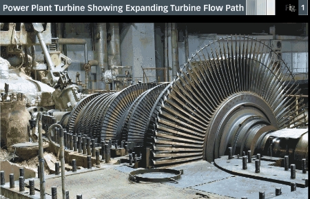
In a steam turbine, the steam’s energy is extracted through the turbine and the steam leaves the turbine at a lower energy state. High pressure and temperature fluid at the inlet of the turbine exit as lower pressure and temperature fluid. The difference is energy converted by the turbine to mechanical rotational energy, less any aerodynamic and mechanical inefficiencies incurred in the process. Since the fluid is at a lower pressure at the exit of the turbine than at the inlet, it is common to say the fluid has been “expanded” across the turbine. Because of the expanding flow, higher volumetric flow occurs at the turbine exit (at least for compressible fluids) leading to the need for larger turbine exit areas than at the inlet. This change in flow area can be seen in the turbine in Figure 1.
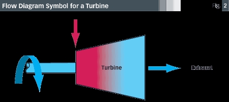
The generic symbol for a turbine used in a flow diagram is shown in Figure 2 (below). The symbol diverges with a larger area at the exit than at the inlet. This is how one can tell a turbine symbol from a compressor symbol. In Figure 2, the graphic is colored to indicate the general trend of temperature drop through a turbine. In a turbine with a high inlet pressure, the turbine blades convert this pressure energy into velocity or kinetic energy, which causes the blades to rotate. Many green cycles use a turbine in this fashion, although the inlet conditions may not be the same as for a conventional high pressure and temperature steam turbine. Bottoming cycles, for instance, extract fluid energy that is at a lower pressure and temperature than a turbine in a conventional power plant. A bottoming cycle might be used to extract energy from the exhaust gases of a large diesel engine, but the fluid in a bottoming cycle still has sufficient energy to be extracted across a turbine, with the energy converted into rotational energy.
Turbines also extract energy in fluid flow where the pressure is not high but where the fluid has sufficient fluid kinetic energy. The classic example is a wind turbine, which converts the wind’s kinetic energy to rotational energy. This type of kinetic energy conversion is common in green energy cycles for applications ranging from larger wind turbines to smaller hydrokinetic turbines currently being designed for and demonstrated in river and tidal applications. Turbines can be designed to work well in a variety of fluids, including gases and liquids, where they are used not only to drive generators, but also to drive compressors or pumps.
One common (and somewhat misleading) use of the word “turbine” is “gas turbine,” as in a gas turbine engine. A gas turbine engine is more than just a turbine and typically includes a compressor, combustor and turbine combined to be a self-contained unit used to provide shaft or thrust power. The turbine component inside the gas turbine still provides power, but a compressor and combustor are required to make a self-contained system that needs only the fuel to burn in the combustor.
An additional use for turbines in industrial applications that may also be applicable in some green energy systems is to cool a fluid. As previously mentioned, when a turbine extracts energy from a fluid, the fluid temperature is reduced. Some industries, such as the gas processing industry, use turbines as sources of refrigeration, dropping the temperature of the gas going through the turbine. In other words, the primary purpose of the turbine is to reduce the temperature of the working fluid as opposed to providing power. For instance, air cycle refrigeration systems produce cold air without the use of organic refrigerants (which may be greenhouse gases) by expanding air across a turbine. Generally speaking, the higher the pressure ratio across a turbine, the greater the expansion and the greater the temperature drop. Even where turbines are used to cool fluids, the turbines still produce power and must be connected to a power absorbing device that is part of an overall system.
Also note that turbines in high inlet-pressure applications are sometimes called expanders. The terms “turbine” and “expander” can be used interchangeably for most applications, but expander is not used when referring to kinetic energy applications, as the fluid does not go through significant expansion.
Compressors
While turbines produce power from a pressurized or high kinetic energy flow, compressors require power to run and transfer this power to a fluid. For instance, bottoming cycles, water purification systems, organic Rankine cycles and dispatchable energy technologies all employ compressors for various reasons. To discuss these energy addition devices, let’s first use “compressor” as a generic term for all similar devices including fans, blowers and pumps. Compressors are typically powered by a rotating device such as a motor or turbine and are used to increase the pressure of a fluid, transport the fluid or — as is most common — a combination of these two. Unlike a turbine, which needs a high pressure or high kinetic energy incoming stream of fluid to operate, a compressor needs only a source of power to cause rotation and will then compress or pump a fluid.
Many potential power sources exist for compressors. Perhaps the most common is an electric motor. Electric motor drives can be low speed (as in a refrigerator), or high speed (as in some industrial applications). High-speed motor drives are becoming more popular as motor technology advances. Compressors also can be driven by a turbine (as in the turbocharger in your car where hot engine exhaust gas drives the turbocharger turbine). For high power applications, an entire gas turbine engine can be used to drive a compressor.
Compressors are typically sized to flow or pump a given amount of gas while raising the pressure of that gas. The amount of pressure rise available from a compressor is usually given by a “‘pressure ratio,” which is defined as the compressor exit pressure divided by the inlet pressure. A compressor design can cover a range of flow and pressure ratio, but within sometimes narrow limits. As the pressure rise through a compressor increases, the flow decreases and vice versa. Any given compressor can sustain only so much pressure rise before the flow through the compressor stalls and the compressor undergoes a phenomenon called “surge.” Surge is an unsteady flow that is mechanically destructive and is to be avoided in normal operation. At the other extreme, as the pressure rise across a compressor is reduced, flow increases, but only to a maximum amount depending on the compressor design.
Generally, compressors have limited operating range and must be sized appropriately for a specific application as they are not able to operate well off-design. Compressors that produce a relatively high volume of airflow at small pressure rise are called fans or blowers. The table fan that cools a room in your home on a hot day displays very little pressure rise across the fan, although the fan will put out as much airflow and velocity as the fan motor will allow. On the other hand, gas compressors usually have a higher pressure ratio, but move a lower volume of flow. For example, the compressor in the turbocharger in a car might have a pressure ratio of 3.0, meaning the air enters the compressor at 14.7 psia and leaves at 44 psia; an increase of 29 psia.

The generic symbol for a compressor is shown in Figure 3 (above). Since compressors increase the density of fluids (if the fluid is compressible), geometric areas through a compressor typically become smaller; hence the exit of the compressor symbol is smaller than the inlet. As compressors add energy to a fluid, the temperature of the fluid increases, as indicated by the coloration of the symbol. Figure 4 (below, left) shows the cross-section of an axial compressor, where the reduction in flow area is visible.

Compressors, fans and blowers are all devices that work on gaseous fluids. By contrast, pumps are energy increasing turbomachines that work on liquids. Pumps are generally similar to compressors in that they increase the pressure of a working flow and also “pump” or move a quantity of liquid typically through a system of piping. As with a compressor, for a given pump design a tradeoff exists between pressure rise and flow rate. An increase in a pump’s pressure rise means the flow rate decreases, and vice-versa. Pressure rise in a pump is usually not referred to as pressure ratio. Instead, pump pressure rise capability is characterized by “head.” In general terms, this refers to the height of a column of liquid that could be supported by the pump, measured in feet or other linear units. For instance, a pump for a household well application might be able to supply a head of 50 feet at 15 gpm.
Pumps have an interesting operational limit not seen in compressors. The inlet to a pump is often called its “suction end” and is typically located where the system pressure is lowest. As fluid is pulled into the pump, fluid velocity increases, and, as described by Bernoulli’s principle, the fluid’s local static pressure decreases. As the local static pressure approaches the liquid’s vapor pressure, the liquid vaporizes or cavitates causing cavitation bubbles to form. These bubbles can implode on the pump blading causing noise, vibration and damage over a period of time. As a result, pumps must be adequately designed and sized to avoid operating in this cavitating mode.
Compressors and pumps can be designed to operate with a wide range of fluids, from air and water to refrigerants to viscous liquids to biomass to supercritical carbon dioxide (CO2).
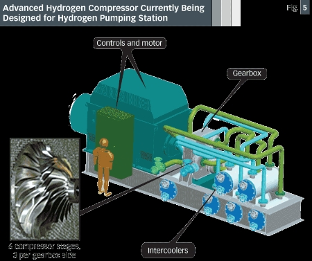
Some fluids are harder to design for than others. For instance, work is being done to develop a new generation of hydrogen pipeline compressors. Gaseous hydrogen is notoriously hard to compress and pump, due to the low density and high turbomachinery rotational speeds required, not to mention issues associated with sealing hydrogen. Figure 5 (below) shows conceptually one of these new compressor designs, in the form of a motor drive compression system, with six stages of a compressor on an integrally geared system. Due to the varying properties of different gases and liquids, a compressor or pump designed for one fluid will likely not work well for other fluids. The fluid properties that impact this usability include density, viscosity and specific heat, as well as design pressure and temperature. Given that compressors and pumps are typically designed for one working fluid and do not have a wide off-design operating range, it is important that the correct compressor or pump design be selected for a given green energy application.
While one might be able to find a selection of “off-the-shelf” water pumps, typically no off-the-shelf compressor selection is available. In addition, many green energy production processes require high turbomachinery performance (efficiency) to be feasible. This means turbomachinery must often be custom designed for the specific application. Fortunately, with well-developed design software and analysis capabilities such as computational fluid dynamics, aerodynamic and turbomachinery specific features, designers have the tools and skills to accurately perform custom design work.
Green energy systems exhibit many needs and uses for compressors and pumps. The most common application for compressors is to raise the pressure of a fluid to move it through the system to the next component (perhaps a heat exchanger). The pressure rise imparted to the flow must be high enough to overcome any downstream losses in the system, while maintaining sufficient pressure for other components in the system. For instance, in reverse osmosis cycles, pumps are needed to pressurize salt water up to 1,000 psi to force the salt water across a membrane where separation occurs.
Several energy systems raise fluid pressure solely for storage or pressurization purposes. For instance, several oil field reinjection systems pressurize gas to be injected back into the ground to enhance oil recovery. On the green energy side, some dispatchable wind turbine cycles use a wind turbine to drive a compressor to compress air. The compressed air is stored in a tank or underground storage facility and is available when needed, to expand across a turbine and drive a generator, for instance.
While this article has discussed mainly the aerodynamic application and performance of compressors and turbines, the mechanical design and construction of these units is also critical to reliable operation with low mechanical losses and low leakage rates.
Daniel Hinch is senior vice president, Engineering and Products at Concepts NREC, a leader in turbomachinery design, research, engineering and manufacturing. Contact Mr. Hinch at dhinch@conceptsnrec.com.
For further reading on turbomachinery basics, please consult these references:
Fig. 4: Cross-section of an axial compressor showing the reduction in blade height and flow area through the compressor (airflow is left to right)
![]() To subscribe or visit go to:
http://www.renewableenergyaccess.com
To subscribe or visit go to:
http://www.renewableenergyaccess.com